MBED, Arduino , STN1110 & BT

I believe you imagine the power consumption will be some uA when the mbed goes to sleep, but it is huge, 127 mA in Sleep mode.

I think we need some power down circuit, as priusfan suggested, including for peripheral devices.

Yoshi@Japan

I would hope that we could get it down into DEEP Power Down 57mA
 
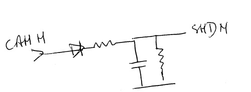
May I suggest a signal detection connected on the canh (or canl) pin.
On this pin connect a signal diode followed by a big resistor and after a capacitor. Connect the capacitor between the regulator's shutdown pin (see priusfan link) and ground one.

What I don't know is : Does connecting these 3 components on the can h will modify the signal ? Resistor may have a high value (390-470k ?), shutdown pin need only more then 6uA.

Total consumption in sleep mode will be 16uA.


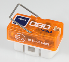
@ccdisce a nice box :
220px-Texa_obd-log.png


I will look further into changing out the 7805 regulator to one that will be able to control from activity on can activity.

A popular way is to use the USB Host power line coming down the USB cable, so if you do not have USB plugged in or your laptop is off, of course the device is functioning autonomously with no Laptop hooked up contoll would have to switch to can activity sensing.

The Data Logger boys have created their own plugs but remember we are using a cable and we have no source of those small cases.

This was a possibility
http://www.carchip.com/Products/8226.asp
 
I think planetaire's idea is good:
it would allow an automatic wakeup as soon as the CAN is active.
so 2009Prius and all would be happy :-D .

in detail : a schottky diode, a resistor (1k should not interfer with the CAN signal) a capacitor and another resistor (high value) // with the cap (for unloading the cap).
14f9f9b7413fb4.jpg


I will try to calculate the RC time....

it is also possible to use a low power schmitt trigger activated when CANH is > 2V...

I will check into the possibility of using the present CAN Transceiver as the monitoring device. I may need to keep it powered up separately but hopefully in Standby mode for LOW power.
 
Here is a paragraph from the Datasheet:

<quote>
1.4.3 STANDBY MODE
The device may be placed in Standby or SLEEP mode
by applying a high-level to the RS pin. In SLEEP mode,
the transmitter is switched off and the receiver operates
at a lower current. The receive pin on the controller side
(RXD) is still functional, but will operate at a slower
rate. The attached microcontroller can monitor RXD for
CAN bus activity and place the transceiver into normal
operation via the RS pin (at higher bus rates, the first
CAN message may be lost).
<quote>

I will have to check further in power requirements.
 
First of all it feels great when so many experts are actively contributing to the discussion. I am rest assured that we will end up with the best, perfect power saving solution. :-D

Now from an end user point of view, it seems a very good idea to base the power saving feature on monitoring the CAN activity. But occasionally the user may take the device out of the car and connect via USB or BT to do setup or transfer files (well I guess in the BT only case one would leave it plugged in but car is off). So the device needs to be able to power ON whenever there is CAN activity OR USB/BT activity. And the device should go to power saving mode a few minutes after BOTH CAN AND USB/BT have become silent. This shouldn't be too hard to do, right? :cool:
 
@2009Prius

This shouldn't be too hard to do, right? :cool:


oh yes, it is not too hard :-D : when connecting the mbed to a computer for updating software or files, the mbed is always powered from the USB (this is a feature and there is no dicussion about this) ... but, in this case, the 3.3V is not present on pin p40, so no possibility for testing BT for instance.
 
idem yoshi : 57mA is too much; a prius stopped uses around 80mA

I have no hope with the can receiver for managing sleep and wake.

I will test with a LM 2575 T-5 and a 74HCT14 for driving the ON/OFF , capacitor 1microF, resistor 5 meg

I should receive them within 3 days
 
Dernière édition:
Hello 2009Prius,
Je suis d'accord avec toi (I agree with you), l'OBDLink en mode ATMA est parfait. J'ai probablement moins d'une erreur toutes les 10 heures !

Les PID sont tous parfaitement cadencés. Mais étrangement pas le 030 ! J'obtiens entre 161.3 et 165.6 fps.

Le PID 039 est parfaitement cadencé : 122.11 fps sur ma Prius.

Je ne suis pas d'accord avec toi, le PID 039 ne correspond pas au couple (that's not the torque). Je suppose que c'est le VVTi. Le couple est donné par le PID 348.
I have been watching PID 348 for the engine torque and it works well except under one condition. When gliding above ~40 miles/hour, the engine spins at ~1000 RPM but no fuel is used. Under this condition I get engine output power ~ 25 kW but it should be ~ 0 kW. What's going on? :eek:


PS. I went back to my notes about OBDLink. The sales person said the current draw is less than 1 mA (when the device is sleeping). But I never measured it myself so can not be 100% sure.
 
I have been watching PID 348 for the engine torque and it works well except under one condition. When gliding above ~40 miles/hour, the engine spins at ~1000 RPM but no fuel is used. Under this condition I get engine output power ~ 25 kW but it should be ~ 0 kW. What's going on? :eek:...

You should get an average of -15Nm (moving between -13 and -17). May be a decoding problem.
It is a 10 bits signed.
 
I do not think that it is hard to do, Let me generate a Visio drawing or better still a schematic in Eagle as I can copy and paste this as a block of schematic into Mpady I need to do a brain dump of the componets that I want to use.
 
nothing new on my side, I am waiting for a BT module since 2 weeks...

So I started on android side to be ready for using the new kind of messages received via BT...

I will also test the possibility to detect the presence for can msg using 74HCT14...
 
nothing new on my side, I am waiting for a BT module since 2 weeks...

So I started on android side to be ready for using the new kind of messages received via BT...

I will also test the possibility to detect the presence for can msg using 74HCT14...

I have set it up using the MCP2551 in Standby mode.
I will post the schematic and board layout in Box shortly.
 
@2009Prius download eagle here .
what is interesting with eagle is the possibility to create sch & brd files....


@winston: the way you create the auto/on switch seems to me really excellent :jap::jap:.
just for info, how many mA, do you think, will be used when sleeping?

what are the IC used for "5V_always" ?

  • the one on the right to create it ?

  • and the one activating the regulator (it looks like a good old 555 8) )...


I will check how to manage deep_sleep with P$24 on the mbed , it should be easy... edit : yes just pull down digital P$24 in init sequence and digital high when detecting end of activity.

edit: control for RSLEW
I would suggest to use 1k for R12
and 100k (at least) for R1 , so the level for pin 8 will be high and not half high when status is "sleeping".
 
Dernière édition:
I took some time having a deep look inside Winston's WORK :jap::jap::jap:.

one question: using optimisation from eagle, what is your opinion regarding groundplanes (respecting free space under BT module) ?

one remark: as there is an UART, initially prepared for receiving datas from a GPS, it could also, on demand, be used for driving an external serial LCD, for instance 4x20. so it would be possible to show, at least, 8 values...
IMHO, it is much more efficient to use a serial LCD, so it is not necessary to loose time (in comparison with // LCD drivers).

one big change: we cannot use VU (P$39) for an external USB , we must instead use standard +5V, this is because this VU is active only when mbed uses his own USB plug
 
Dernière édition:
I got EAGLE installed and working. Thanks priusfan!

By the way I am looking at PID 230 description on kinetik's web site. Is the unit 1 cm exact or 1.016 cm? It seems to reset to 0005 at the beginning of each trip, is this right? Thanks!
 
If it's not too much trouble please convert to google Sketchup format. Thanks!

OK I will run the SketchUP ulp and generate an new zip file as I added CAN_RX to mbed port pin23. This was done so that the mbed can detect CAN activity without having to use the CAn engine
 
@2009Prius download eagle here .
what is interesting with eagle is the possibility to create sch & brd files....


@winston: the way you create the auto/on switch seems to me really excellent :jap::jap:.
just for info, how many mA, do you think, will be used when sleeping?

what are the IC used for "5V_always" ?

  • the one on the right to create it ?

  • and the one activating the regulator (it looks like a good old 555 8) )...


I will check how to manage deep_sleep with P$24 on the mbed , it should be easy... edit : yes just pull down digital P$24 in init sequence and digital high when detecting end of activity.

edit: control for RSLEW
I would suggest to use 1k for R12
and 100k (at least) for R1 , so the level for pin 8 will be high and not half high when status is "sleeping".

1.
Sleeping the target current was 2.5mA. Adding the numbers up it should be around 1.0mA to 1.1mA

2.
A zetex ZLDO330 is used to generate the the 5v_always. In Eagle right click on the part and the tab will indicate the name.

3.
Sorry the sizing on the resitors for slewing and stanby pull up were not set correctly. What I was thinking of was 10K for R1 to give us a resonably high slew rate to handle the can bus when working normally and when in standby the 2k would pull the can receiver into standby mode. So we would then watch the can bus for can activity which woulf fire off the 555timer and turn on the big LDO.
Can activity can be confirmed on mbed pin23 by looking for highs, lows, rising edges, falling edges etc.

Yes a new CMOS version of the 555 timer is used in a re-triggerable mode and the timeout is set for minutes.

Standby would consists of 2 stages:

1. Transition the can reciver to standby set the approriate pin high I may have to add a cmos FET in series with R1 so as not to use an aditional 0.5mA for this function.
2.Once the 555 timer times out the power should drop to 1.1ma or 1.1+0.5mA for the standby driver.
 
priusfan,

for the Bluetooth module ground plane underneath is OK except for the antenna area which I have now kept copper free. Good catch.

w.
 
I took some time having a deep look inside Winston's WORK :jap::jap::jap:.

one question: using optimisation from eagle, what is your opinion regarding groundplanes (respecting free space under BT module) ?

one remark: as there is an UART, initially prepared for receiving datas from a GPS, it could also, on demand, be used for driving an external serial LCD, for instance 4x20. so it would be possible to show, at least, 8 values...
IMHO, it is much more efficient to use a serial LCD, so it is not necessary to loose time (in comparison with // LCD drivers).

one big change: we cannot use VU (P$39) for an external USB , we must instead use standard +5V, this is because this VU is active only when mbed uses his own USB plug

1. No ground plane under antenna area.

2. I will add a 3 pin header to attach a serial LCD in parallel with the GPS may want to use a demux.

3. Ok I will move the USB Host power to the Linear tech LDO 5v output.
 
one big change: we cannot use VU (P$39) for an external USB , we must instead use standard +5V, this is because this VU is active only when mbed uses his own USB plug
:oops: this is totally wrong , exactly the opposite....

but no change for the design: take +5V where it is easier....
 
Pages vues depuis le 20 Oct 2005: 311,548,902
Retour
Haut Bas