MBED, Arduino , STN1110 & BT

OK I will run the SketchUP ulp and generate an new zip file as I added CAN_RX to mbed port pin23. This was done so that the mbed can detect CAN activity without having to use the CAn engine

In fact, I think it is not necessary:
can activity is managed by ISR , and the mainloop is only waiting for one interrupt to do something.
 
regarding x4 (connector for lcd-serial),
I do not think it is usefull because we have already U3 for GPS and I cannot imagine using both, at the same time, sharing the same UART..
anyway there is a missing GND in X4-4.

regarding P$24: as you manage completely the deep-sleep, I have nothing to do in the program (I will leave it high impedance) :-D

addendum:

it seems it is better to add 2 15k resistor to GND for D+ D- to detect connection on USB HOST
2 x 15k resistors are needed to pull the USB D+ and D- to ground when you configure the mbed USB controller as a host.
extract from this link
 
also, today I played with eagle and the brd, I tried to apply the drc rules from sparkfun.

some remarks:
the holes from X2 & X3 are not "protected" so we can get some funny things when trying ratsnest.
P$23 is used (not a problem, it can be programmed as a digital input).
the clearance is very very tight for many traces.

anyway, this was just for fun, as I am not able to work with SMDs...

Do you have an idea of what could be the cost for such a mounted card (witout the mbed) ?


I do not know why you want to run a DRC with a DRC from another project and expect not to get 'funny things' .
The spacings, clearances and trace widths are set up in a design file and the settings are dictated by the board fab house.

I saw the problems with the non "protected' areas of X2 and X3 and had to manually route some traces around the 'keep out' areas as the experienced CAD folk call them.
The X2and X3 parts came from the Eagle Libraries and KEEPOUTS should have been designed in there when the parts were designed.
At some time the parts in the Library should be updated to add keepouts.

Aww.... anyone can work with SMDs all you need is a microscope, good soldering iron, a steady hand and patience/time to create models.

I ran the design through the submittal process at BATCHPcb's BOT and the bare boards were around $22USD 2week turn, 1week ship for PCBs etched in China.
I have not generated the BOM cost yet.
Now that the changes have stopped I will start on the BOM Excel Spreadsheet costs based on DigiKey prices for a 10pc build tonight.
 
some news:
I tested RTC with a backup battery: OK

I tested SDHC card (4GB) with another library : OK

I tested Bluetooth RN42 : OK now, connexion with an android device is automatic.

BUT, I spent one full day before discovering

  • RN_13 should go to mbed_28

  • RN_14 should go to mbed_27


I made a quite big change in the init sequence to read all the parms from only one file. (to be fully checked).
the file looks like:
// this is a parm file for CANHSD
// lines starting with / are comments
// short lines are ignored
// need a space after the last code, max line length 128
// the first word is the parameter

// Set RTC time to 26/04/2012 @ 07:37:52
TIME 1335425872

// set loglvl //0=verbous 1=detail 2=no detail
LOGLEVEL 1

// Hardware
USE_BT 1
USE_SD 0
USE_BMP 0
USE_LCD 0

// filters ID & Mask
FILTER 0B4 FF// this frame will give the exact speed
FILTER 1C4 FF // ICE RPM
FILTER 230 FF
FILTER 245 FF // acc pedal
FILTER 3D3 FF // fuel flow L/H
FILTER 498 FF // coolant temp
FILTER 4A6 FF //
FILTER 63B 03 //
FILTER 7E0 00
FILTER 7E2 00
FILTER 7E8 00
FILTER 7EA 00

// Requests
// 1 pos is ECU , second is period and FULL Message

REQUEST 7E0 1 02 21 3C 00 00 00 00 00 // Inj
REQUEST 7E0 1 02 21 49 00 00 00 00 00 // ICE torque
REQUEST 7E2 1 03 21 61 67 00 00 00 00 // MG1 rpm, torque, temp
REQUEST 7E2 1 03 21 62 68 00 00 00 00 // MG2 rpm, torque, temp
REQUEST 7E2 1 03 21 8A 74 00 00 00 00 // Amp
//REQUEST 7E2 1 02 21 74 00 00 00 00 00 // BC temp, VLB VLH now combined with previous

REQUEST 7E0 10 04 01 06 07 0E // STF LTF IGN_adv
REQUEST 7E2 200 02 21 01 00 00 00 00 00 // SoC

REQUEST 7E0 400 03 01 3C 3E 00 00 00 00 // Cat temps
REQUEST 7E2 401 03 21 70 71 00 00 00 00 // Inv temps

REQUEST 7E2 500 02 21 87 00 00 00 00 00 // Batt temps
REQUEST 7E2 500 02 21 98 00 00 00 00 00 // DCL CCL
 
Thanks for the continuing effort to make it better. :)
 
@2009Prius
I need your help :?:

there is something wrong when I use vector...

here is the release I am testing.

here is a log:
PID=7E0 freq=001 Code= 02 21 3c 00 00 00 00 00
PID=7E0 freq=001 Code= 02 21 49 00 00 00 00 00
PID=7E2 freq=001 Code= 03 21 61 67 00 00 00 00
PID=7E2 freq=001 Code= 03 21 62 68 00 00 00 00
PID=7E2 freq=001 Code= 03 21 8a 74 00 00 00 00
PID=7E0 freq=010 Code= 04 01 06 07 0e
PID=7E2 freq=200 Code= 02 21 01 00 00 00 00 00
PID=7E0 freq=400 Code= 03 01 3c 3e 00 00 00 00
PID=7E2 freq=401 Code= 03 21 70 71 00 00 00 00
PID=7E2 freq=500 Code= 02 21 87 00 00 00 00 00
PID=7E2 freq=500 Code= 02 21 98 00 00 00 00 00
debug:1,89,88,0000024B,t0B4800000000000000BC
0B400000000000000BC
debug:2,89,87,00000B71,t245500000080CC
24500000080CC
T 10008000 E7 E7 E7 E7 E7 00 00 F0
so, to make it short, it seems I am putting garbage in the init sequence when trying to store the requests....

or there is a mix in vars when I try to get them back...

of course your comments, on what I tried to realize, are most welcome.. . :-D

also, I have a small problem with the dispatcher (something with * or & to pass a string to a function);
tonight, I will go back to my big C++ book...
 
Dernière édition:
Hi Priusfan, I have'nt been following your project so far (though I have to admit that I'm interested :-D); but because I had to write some C++ code again for work (after over 10 years), I thought I'd have a quick look at your code:
What I see is a global variable reqTable declared line 61 and then in init() you fill up a different variable reqtable (declared line 202) that you fill up but then don't seem to use anywhere...
May I suggest you if you really need this second variable to rename it so that the difference in the name is more than just the upper/lower case 'T'?
I'm not sure what your problem is but it looks weird to fill a vector that will be destroyed when you exit init(), my guess is that you should remove reqtable and use reqTable everywhere.
---Edited to add:
Im' not sure what your question is about * and &:
void myFunc(string * pStr) is called like this: string toto; myFunc(&toto); (it passes the address of toto and my Func has a pointer to a string)
void myFunc(string& str) is called like this: string toto; myFunc(toto); (it passes a reference to toto, avoiding the copy-constructor).
 
HELLO ;) Guinness :jap:

nice to "see" you again & thx for your very helpfull remarks*...

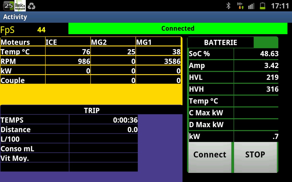
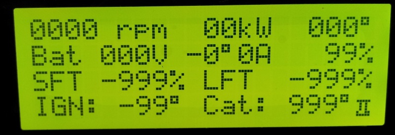
here is a preliminary result on a galaxy note:
14faed1463887e.png


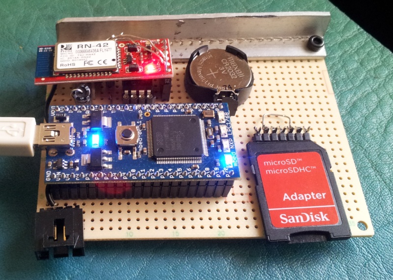
to make it short: with this kind of interface:

  • we can ask for more than 100 request/seq.
  • we can use selective passive frames.
  • using BT, the result is easy to use for any kind of platform.
  • it is possible (to be checked) to log on SDCard.
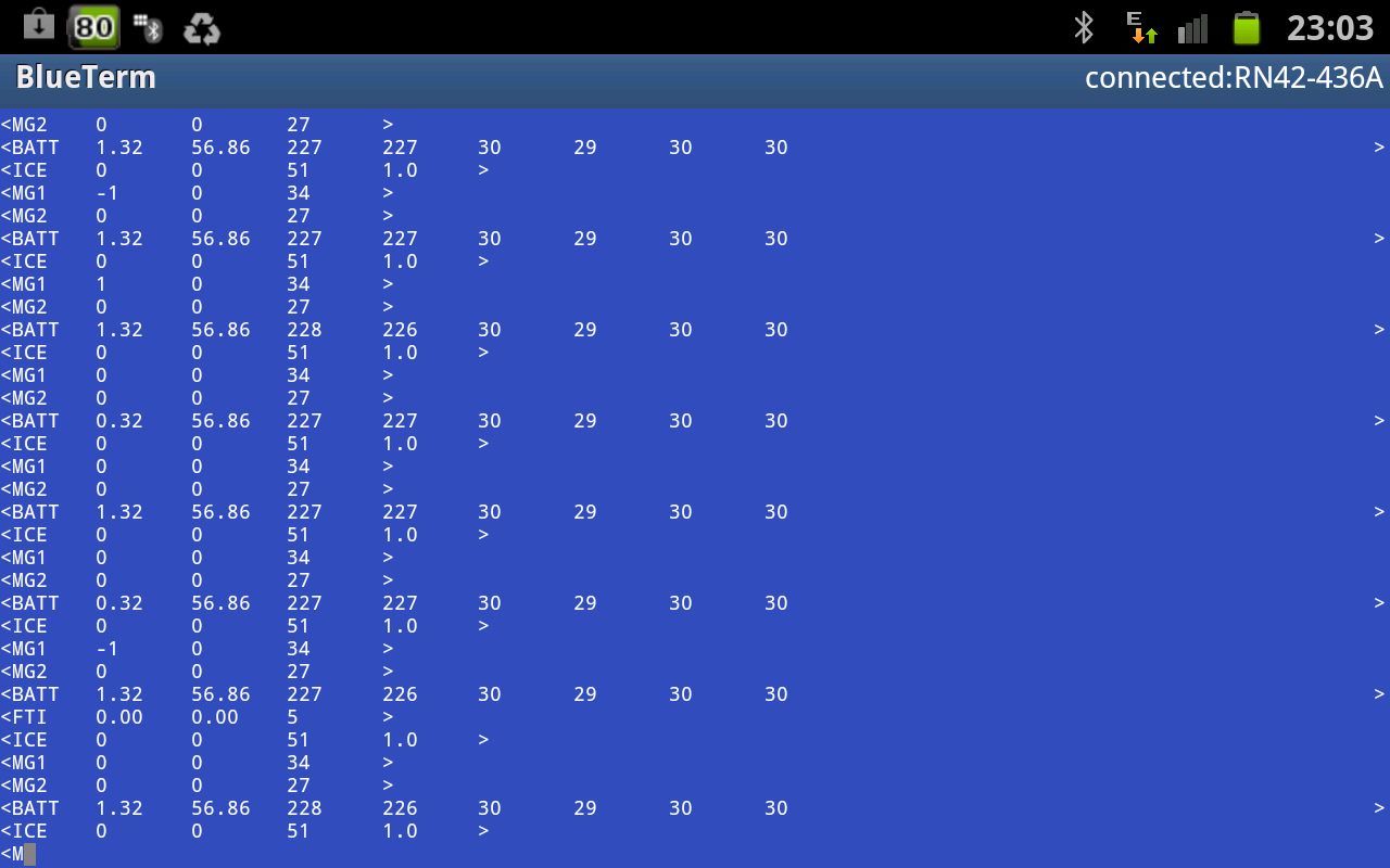
on a gen3, regarding ICE, MG2 & MG1 we get around 11.5 FULL info/sec


as you can see, it will be much easier than using an elm327 or stn1110, there is no latency, and the data are already pre-formatted.


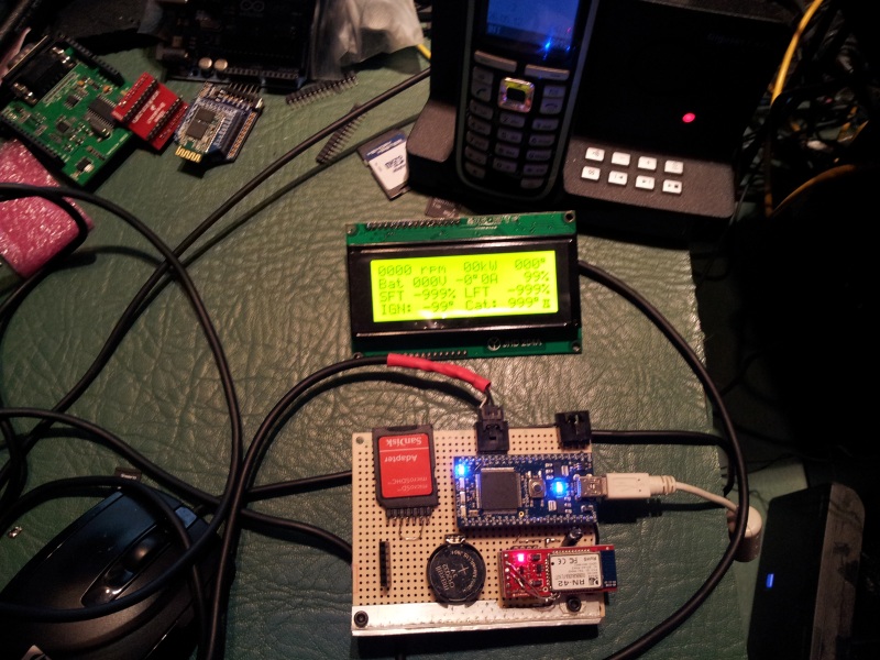
regarding BT: the interface is "broadcasting", without waiting for a "listener" :
I start the car, I start my app on android (or whatever OS) and I get the messages...


and here is a log of what we get by USB (at the same time); the timestamp comes from realterm.
the car was not moving very fast in my garage :-D, so I will do some more tests tomorrow.

* you wrote :violon: you had no practice with C++ since 10 years :-D

I write : I never practised C/C++ before this "thing", but knowledgeable :jap:people were there to correct my mistakes...:velo:

ps: the main trouble I had
I was feeding BS in the requests
PID=7E2 freq=001 Code= 03 21 8a 74 00 00 00 00
PID=7E0 freq=010 Code= 04 01 06 07 0e
PID=7E2 freq=200 Code= 02 21 01 00 00 00 00 00
the line in the middle was not complete....:oops:
 
priusfan,

Fixed the BT connections.
Added the usb host pull-downs.
Found and fixed the missing GND on the LCD connector earlier when I ran the ERC.
Fixed ERC errors caused by Model usage.
Routed around the holes in x1,x2.
Added GND stiching to incorporate orphaned Copper Pours.
Fixed DRC errors.

Which CAN Port is being used?
 
To get another run into BATCHpcb I will just use the mbed 29 30 that we have been using. Just checking.
 
can port: I use p29 p30...

I made some cleaning in the project. it is here
this morning, I made a short test with a 31 minutes stop;
the system recorded (and closed automatically) 2 files on the SDCard.
one is here, the second there
the parm file used is this one

it will be very easy to adapt an automatic logrotation for instance every 30 minutes...

the file recorded on SD has the same content as what is sent via USB or via BT. so the client app could show realtime info or use a replay function reading a logged file...

the 7805 reg on my test card was really hot, so I added a "radiator"
14fafc4b269b0d.jpg


the rn42 is a 5V sparkfun model, so I connected directly pin 13 & 14 to the connector to bypass their level converter...

now, the system is waiting for somebody to write gen2 rules & calcs...
 
Sorry the weekend was crazy and I haven't checked in until now. But looks like you have been taken care of and are making good progress. Great!
 
and now, a first test on an android device (galaxy note)...
at this time, this is just a proof of concept (check usage of frames received via BT).


14fb526765b1c7.jpg
 
Very very good work. I read last messages (I was late) and I can only applause.
 
priusfan

<the 7805 reg on my test card was really hot, so I added a "radiator">

The SmartBase board does warn of the heat.

Maybe we should be thinking of a switching regulator to take the power use efficiency
from 33% to 90%. I have used simple monolithic switchers before so I will look into this.
 
I have, waiting in a drawer, a switching regulator for this purpose, but not yet the right inductor ...

coming back to a board, I think ethernet plug will never be used in a car; IMHO, it could be either BT or Wifi.

also, as now,it is possible to use efficiently a SDCard, the use of MBED is less necessary, and it could be possible to use a lpc1368 instead.


@this time, I am playing with the odometer.
I am implementing the use of PID 230 as explained ky kinetik:
uint16_t wi, ww, wprev, nb230;
uint32_t distcm;
case 0x0230 : {
ww= wrk[0]*256+wrk[1];
if (firsttime) {
wi=ww;
nb230=1;
firsttime=false;
wprev=wi;
}
if (wi < wprev) {
nb230++;
}
wprev=ww;

}
break;
distcm = odo_coef * (nb230*65535-wi); // distance since start in centimeters (max: 4294967295)
uint16_t distkm=distcm/100000; // distance in kMs (max 42 949 kMs)
I will also use a odo_coef in the parm file to correct the real distance according the tyres.
this parm will look like:
odo_coef 0.974 // or 1.016 for instance

I am also waiting for a LCD serial (4 x 20), it was shipped from england 10 days ago....
 
somes fresh news:

today, I drove around 250kms with some stops, using the system for datalogging on SDCard.

  • the RTC works perfectly since 2 weeks

  • the log rotation works well,

  • the system was perfectly stable.
when looking at sdcard's content from a pc, there is no date and no size for the files,
but the name contains a kind of timestamp, and it is possible to open them with any kind of tool, so it's ok.

the formula for the odometer (from previous msg) is erroneous.
it is corrected now.
also, I changed the periodicity for log_rotation to 20 minutes instead of 30, because in 30 minutes, I get more records than excel 2007 allows (65535).
at this time, a 30min' log has a size around 2mB.

tomorrow, ( as my wife will use the prius) I will start playing with a serial LCD.
I would like to be able to show between 8 & 10 vars on the screen.
a good point with a serial LCD (compared with a standard one) : there is a small buffer (80 bytes), so (if we are carefull) we will not loose any time in the routines for printing on LCD.
 
Hello Priusfan,

Still interesting by the excellent result.
Until now, do you have an idea of the price for the logger with an LCD unit plz ?
 
tests with a serial LCD
14fc1dab694255.jpg


14fc1dab6606fa.jpg


ok, it works...
it is this product : http://doc.byvac.com/index.php5?title=Arduino_BV4308

it is easy to connect : only 3 wires , ground, +5V & TX (p13)
it contains a small buffer (80 cars),
it is easy to program the position for text or numbers.

for testing, I added a diode between VU & 5V, so I can use +5V when connected via USB only.


I also ordered (for tests) this board ;
it is quite cheap (half the cost of mbed),
there is a good power reg,
the can transceiver is already there,
there is also a micro-sdcard,
it has the arduino formfactor, so it is easy to find a nice box.

it will not allow using CAN & USB at the same time,
there are only 13 filters for CAN.
so, if it works, it would allow logging on SDcard, and send infos via BT or to a serial LCD.
90% of program would be the same as with mbed.
 
when looking at sdcard's content from a pc, there is no date and no size for the files,
but the name contains a kind of timestamp, and it is possible to open them with any kind of tool, so it's ok.
Hi,

Have you tried to use ChaN_FS library?
http://mbed.org/users/NeoBelerophon/notebook/chan-fs-/
It supports timestamp and long filename.
the formula for the odometer (from previous msg) is erroneous.
it is corrected now.
I assume you are reading CANID:0x230.
I prefer to read CANID:0x0B4.
Code:
    case 0x0B4:                 // speed, trip distance
        memo_speed = data[tmptail][5]*256 + data[tmptail][6];

        temp = (data[tmptail][4] & 0xFA) >> 2;
        if ( temp < prev_trip ) {
            memo_trip_sub++;
        }
        prev_trip = temp;
        memo_trip = memo_trip_sub * 64 + temp;
        break;
The upper 6 bits of CANID:0xB4[4] shows the trip distance.
The right shifting ( >>2 ) number changes as 0->1->2 .. 62->63->0->1->2 and so on.
The accumulated 5096 count of memo_trip becomes the exact 1km trip distance.

Yoshi
 
@yoshi:
I will try to compare the precision using your formula and what I get from PID 230.
here is the formula I am using:
Code:
static uint32_t wi,ww,nb230,wprev,distcm;
...
 case 0x0230 : {
            ww= wrk[0]*256+wrk[1];
            if (firsttime) {
                wi=ww;
                nb230=0;
                firsttime=false;
                wprev=wi;
            }
            if (ww < wprev) {
                nb230++;
            }
            wprev=ww;
            distcm = nb230 *  65535 + ww -wi;  // distance since start in centimeters
        }
        break;
about chan_fs, I made a test some time ago, and it was not successful, I will try again later.

about LCD, it is working, but I will round up & smooth some vars to avoid a buffer overflow.
I print vars only when the value changes,
for rpm, I will use a roundup to 50rpm
amp's value is changing all the time, I will use also a roundup to 1 amp and a smoothing on 5 values (I get 11,6 values / sec).
 
Pages vues depuis le 20 Oct 2005: 310,732,865
Retour
Haut Bas