MBED, Arduino , STN1110 & BT

I prefer cable also, for the same reasons that priusfan has spelled out. Size is not a huge concern for me either. Thanks!

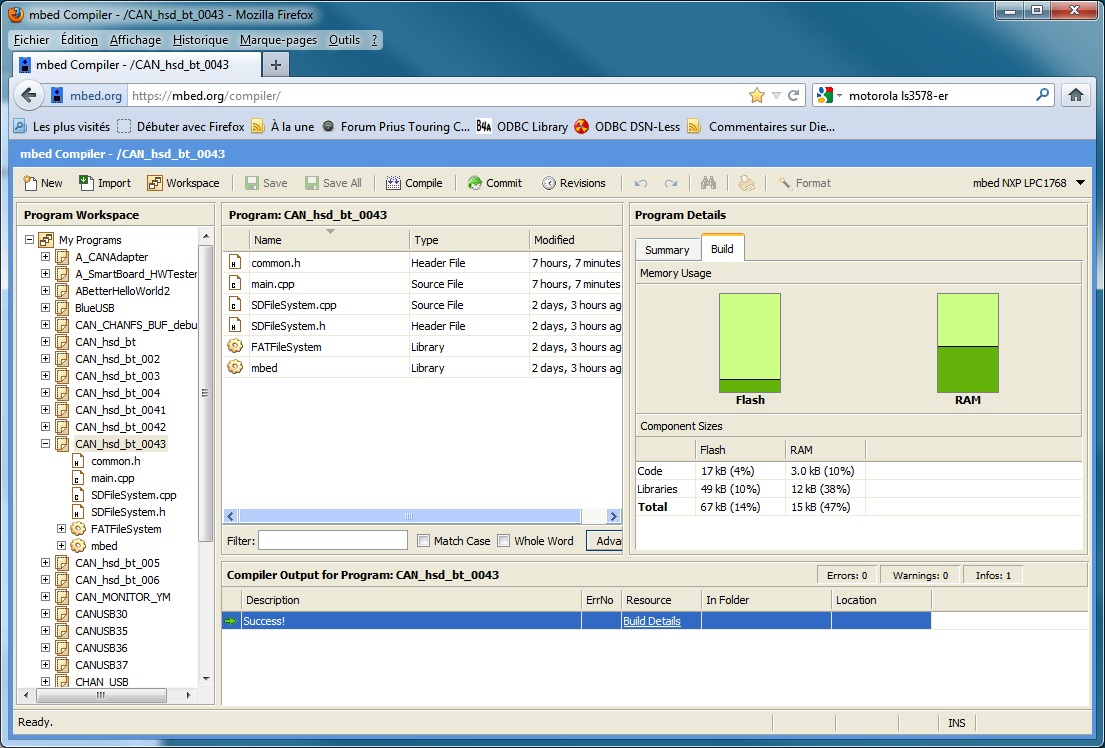
@priusfan, could you take a look at the size of the compiled binary for mbed? (as an estimate of non-volatile memory needed). Thanks!
 
regarding ram usage, have a look at this image:
ram_usage.jpg


the .bin itself has a size of 68 324 bytes.

the source is in the FTP.
main mods:
use a watchdog to close file on sdcard when there is no more traffic (works as intended).
use boolean vars according hardware. ( I will add one for BT).
use a var for loglevel.

after connecting more than 60 times my testbench in the car (and blowing twice the DLC fuse:velo: ),
I will build another one:

  • with a real DLC plug,

  • with a CR2032 (with holder) for RTC backup,

  • with a real sdcard holder,

  • with a real RN42 BT module.
it should be ok for the end of the week.

another bad surprise: the timer allways gives a zero result... (this info is interesting for checking time between frames). this a mbed bug according their forum...
 
pressure from the CAN: we can get it on one byte, that is useless...

about using a cable or attaching the interface straight on the DLC, I would prefer with a cable:
the need to make it very small would be less (so it would be much less expensive).
it would be easier to reach for accessing sdcard.
it would be easier to see led status.
it would be possible to use a ON/OFF switch.


about the speed for BT : if we send only results (see my msg from 21) , 115200 is enough.

Cable will cost around $12USD
PCBs are sold on an area basis so larger PCBs are more expensive
Yes accesing uSD card would be easier
Yes seeing LEDs would be easier
A good on/ sff toggle switch is going to be around $4USD
I checked into Bosch Pressure sensor around $7 in 10pc pricing

I should have BOM done by the weekend.
 
I made small changes in the program, (bugs with time).
it is in the ftp.
there is also a log from sdcard; with actual parms, it stores 900 Bytes / sec.
 
The CR2032 will not fit between the rows of pins for the Mbed.
The SmartBaseboard uses a CR1220 sized battery at one end of Mbed.

I have an extra SmartBaseboard blank that I could send you Par Avion if you will use it.

w.
 
Yes, definitely I am interested...
I send you my address by PM.
 
Priusfan,

I have a New Layout routed and it needs to be checked prior to ordering boards.

Delivery from BatchPCB is going to be around 3 weeks for the price we want to pay.

Board is approx 7.5cMx7.5cM.

Should I send prints to you?

w.
 
I am also interested to see the New Layout and schematics.
Just a quick note if the BMP085 is wired from scratch.
Ideally, the two power pins should be supplied power and filtered separately to prevent digital noise feeding into the analog circuitry.
Yoshi@Japan
 
Yes I read that app before I added it to the circuit, ( guess where the PCB footprint came from? as I did not create the one I used ) and you guys will need to tell me which pin to use for the EOC (end of conversion) interruupt.
At the moment it is NOT connected.

Good hint on the Analog Vddd filtering, I will add a inductor an cap as this is the way I do it at work.

I will post a link to the Eagle files.
 
Y'all should be able to access the Eagle files at

http://www.box.com/s/01a39b3ee51bb853641f

I have included the Google SketchUP file also.

The EOC for the barometric pressure sensor interrupt and the GPS tx and rx need to be specified by the SW folks.
Addes Ethernet connectivity for future requirements.
w.
 
Dernière édition:
bonjour
EOC: could go anywhere from p15 to p24
GPS: rx to p14; tx (if used) to p13

there are 2 resistors and 1 cond on CAN to be removed : R7, R8, C4.
they are used only for end node...
 
automatic control for power

@ccdisce: would it be possible to use a fully automatic (low power) control to avoid the switch?

the question may look stupid ( last time I was working professionally in electronic design was 34 years ago), but the idea would be to use a device of this kind and to control the SHDN pin from a low power voltage comparator with an RC Time between 2 to 10 seconds for shutting down.

we know that when power is on, on prius, the voltage is around 14V so using a low power comparator with a 13V (adjustable) threshold, we could activate / shutdown the interface....
 
Stft ltft ign

I tested the CAN messages for
Short term fuel % trim—Bank 1
Long term fuel % trim—Bank 1
Timing advance
using standard OBDII requests in a combined request.
7E0 10 04 01 06 07 0E // STFT LTFT IGN_adv
where 10 is the periodicity (around 1/sec)

usage:
Code:
            if (wrk[1]==0x41 && wrk[2]==0x06) {
                double stft=  (wrk[3] -128) * 100 /128; // Short Term Fuel Trim 01 06       (A-128) * 100/128
                double ltft=  (wrk[5] -128) * 100 /128; // Long Term Fuel Trim 01 07        (A-128) * 100/128
                int ign= wrk[7] / 2 - 64;               // Timing Advance 01 0E             A/2 - 64
                pc.printf("<FTI\t%3.2f\t%3.2f\t%d>\r\n",stft,ltft,ign);
                if (use_sdcard && fileopen) {
                    fprintf(fp, "<FTI\t%3.2f\t%3.2f\t%d>\r\n",stft,ltft,ign);
                }
            }
result is perfect.

it could be interesting for people playing with ethanol....
It was tested on gen3, should work exactly the same on gen2...
 
Regarding the "auto-on/off" feature that priusfan suggested... If possible I would prefer to be able to activate the device independent of the power state of the car. At least I would like the device to function normally in IG-ON (not READY) mode - the 12 V bus is supplied only by battery and can droop down to 10 V if heavily loaded. I would use this feature from time to time to check the health of the 12 V battery. Thanks!
 
@2009Prius no problem...

my idea was just to avoid draining the small batt if/when we forget to switch off the interface...

anyway, we are here to share know-how & ideas...
 
Hi all,
EOC: could go anywhere from p15 to p24
If we detect the EOC signal by interrupt, the p19 and p20 can not be used.

Regarding to CAN connector, the CAN232 pin compatible is preferred.
2 - CANL
3 - GND
7 - CANH
9 - 12V

Yoshi@Japan
 
Hi all,

If we detect the EOC signal by interrupt, the p19 and p20 can not be used.

Regarding to CAN connector, the CAN232 pin compatible is preferred.
2 - CANL
3 - GND
7 - CANH
9 - 12V

Yoshi@Japan

Yoshi,

Ok I will wire the connector this way instead of the other 'standard'

w.
 
priusfan,

I thought I came across a a way to put the chips to SLEEP when there is no CAN activity?

The USB2.0 specification call for the USB to the Laptop to go to SUSPEND.

w.
 
I think that sensing the lack of activity on the CAN bus could be used to go to sleep.
w.
 
bonjour
EOC: could go anywhere from p15 to p24
GPS: rx to p14; tx (if used) to p13

there are 2 resistors and 1 cond on CAN to be removed : R7, R8, C4.
they are used only for end node...


Ok I will use p15 for EOC
gps_rx p14
gpf_tx p13

No these resistors and cond were suggested by NXP for DC restoration as the are 1.3K connected to Vref of the CAN driver.

w.
 
I think that sensing the lack of activity on the CAN bus could be used to go to sleep.
I believe you imagine the power consumption will be some uA when the mbed goes to sleep, but it is huge, 127 mA in Sleep mode.

I think we need some power down circuit, as priusfan suggested, including for peripheral devices.

Yoshi@Japan
 
Analogic command sleep mode

May I suggest a signal detection connected on the canh (or canl) pin.
On this pin connect a signal diode followed by a big resistor and after a capacitor. Connect the capacitor between the regulator's shutdown pin (see priusfan link) and ground one.

What I don't know is : Does connecting these 3 components on the can h will modify the signal ? Resistor may have a high value (390-470k ?), shutdown pin need only more then 6uA.

Total consumption in sleep mode will be 16uA.


@ccdisce a nice box :
220px-Texa_obd-log.png
 
I think planetaire's idea is good:
it would allow an automatic wakeup as soon as the CAN is active.
so 2009Prius and all would be happy :-D .

in detail : a schottky diode, a resistor (1k should not interfer with the CAN signal) a capacitor and another resistor (high value) // with the cap (for unloading the cap).
14f9f9b7413fb4.jpg


I will try to calculate the RC time....

it is also possible to use a low power schmitt trigger activated when CANH is > 2V...
 
Pages vues depuis le 20 Oct 2005: 313,229,494
Retour
Haut Bas